Or helpful tips for advanced users. An alternative way of modifying AMI BIOS to support processors in the LGA771 construct How to get bios from an exe file
Hello, dear readers of the site! My name is Roman Navat and I present to your attention the third and final part of the article on recovering damaged BIOS firmware (using the example of Acer Aspire E1-532 laptop). Before reading this part of the article, it is recommended that you familiarize yourself with and, in which we disassembled the Acer Aspire E1-532 laptop, removed the motherboard from it, connected the CH341A programmer to the BIOS chip and saved the damaged BIOS firmware in a separate file. Let's continue our work by preparing a new BIOS firmware file and then write it to the BIOS chip.
Recovering a damaged BIOS firmware on a laptop with a programmer, if the laptop does not boot. Part 3. Extracting BIOS firmware from exe file to update BIOS. Editing the firmware file in the HEX editor and writing it to the BIOS chip
Let's go to the Acer website to the support page for the Acer Aspire E1-532 laptop.
And we will download all available BIOS firmware.

For example, let's open the folder with firmware version 2.10.

In this folder we see a regular exe file, run it.

After running the V5WE2210.exe file, we get this error window, which says that this BIOS firmware is not suitable for this laptop or computer. Do not press the OK button yet, since we need to extract the BIOS firmware file for our laptop Acer Aspire E1-532 from the V5WE2210.exe file.

Go to section C: along the way
C: \ Users \ Username \ AppData \ Local \ Temp (the username can be anything depending on the name with which the account was created). In the Temp folder, we see the temporary 7zS2C4E.tmp folder, which appeared after launching the V5WE2210.exe file.

Open the 7zS2C4E.tmp folder and see the isflash.bin file in it, which is the BIOS chip firmware file. Let's copy this file to a USB flash drive.

The isflash.bin file copied to the USB stick.

The size of this BIOS firmware file is 9.45 MB.

When we try to open this firmware file in the CH341A-USB program, we get a message that the file size is larger than needed, that is, this firmware file is too large to be used for flashing the Winbond W25Q64FV chip (namely, this chip is installed on the motherboard of the Acer laptop Aspire E1-532).

Microcircuits can be of different sizes, consider this using the example of Winbond microcircuits. As you can see from the table, the volume of the microcircuit can be 512, 256, 128, 64, 32 Mbit and so on.

The W25Q64FV microcircuit has a capacity of 64 Mbit (or 8 MB).

Since our BIOS firmware file isflash.bin extracted from the exe file above weighs 9.45 MB, and the size of the BIOS chip on the motherboard of the Acer Aspire E1-532 laptop is 8 MB, we need to reduce the isflash.bin file from 9.45 MB to 8 MB. For these purposes, we will use a hex editor, for example HxD. Go to the address
https://mh-nexus.de/en/downloads.php?product=HxD20
and download the installation file of the hex editor HxD

Click on the downloaded file and start the installation.


Install.

Installation completed.

Click on the HxD hex editor shortcut and launch it.

Main window HxD.

Click on File-Open.

Select the isflash.bin file and click "Open"

We get the following.

In the same way, open the file of the damaged BIOS firmware isflash01.bin (which we saved in the second part of the article).

Let's take a closer look at the structure of the isflash01.bin file. As you can see, the firmware file isflash01.bin starts with FF values (line 00000000), and line 00000010 contains the values 5A A5 F0 0F.

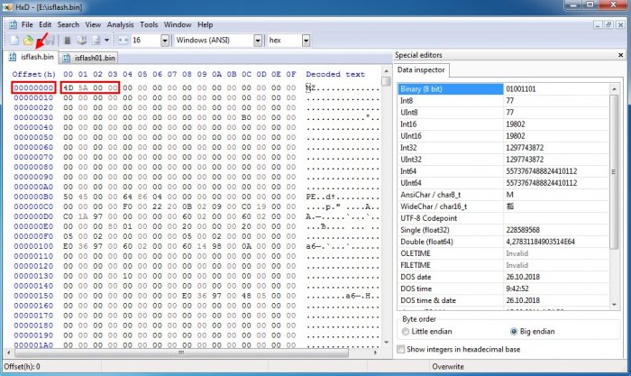
Now let's look at the structure of the isflash.bin file. We see that this firmware file starts with the values 4D 5A 00 00 (line 00000000). We need to make the isflash.bin file start exactly the same as the isflash01.bin file, that is, the FF values (line 00000000) are the beginning of the isflash.bin file.
In the open file isflash.bin, click Search-Find.

And we search for the value 5A A5 F0 0F.

We see that the value 5A A5 F0 0F in the isflash.bin file is in line 0001F340, and above in line 0001F330 we see the FF values.

Select the line range 00000000-0001F320 in the isflash.bin file. To do this, select Edit-Select block.

We indicate the starting (00000000) and ending (1F320) lines of the selected range.

The selected range of strings is 00000000-1F320.

Delete the selected range of lines from the isflash.bin file by clicking Delete.

As you can see, after deleting the selected lines, the firmware file isflash.bin now starts in the same way as the isflash01.bin file, namely, line 00000000 contains FF values, and line 00000010 contains 5A A5 F0 0F values.

Let's go back to the firmware file isflash01.bin. Scroll to the end and see that it ends with the line 007FFFF0.

If you scroll to the end of the isflash.bin file, you will see that it ends with the line 009548F0.

Let's delete all lines from the isflash.bin file that are in the range 00800000-9548F0, that is, we will make the isflash.bin file end with the line 007FFFF0. Click on Edit-Select block.

We indicate the range of selected lines.

The selected line range is 00800000-9548F0.

Delete the selected range 00800000-9548F0 by clicking Delete.

As you can see, now the firmware file isflash.bin ends with the line 007FFFF0.

Let's save the BIOS firmware file under a new name by choosing Save as ...

Specify a name, for example isflash_new and click Save.

The new BIOS firmware file isflash_new.bin.

Please note that the isflash_new.bin file weighs the same as the isflash01.bin file that we saved in the second part, namely 8 MB.

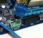
Since the W25Q64FV microcircuit, as mentioned above, has a volume of 64 Mbit (or 8 MB), and our edited firmware file isflash_new.bin weighs 8 MB, then we can proceed with the flashing. We connect the CH341A programmer to the BIOS chip in the same way as we did in the second part of the article.

We launch the CH341A-USB program. We indicate the manufacturer and model of the microcircuit and delete the old BIOS firmware by clicking "Erase".
How do I extract the Dell BIOS files?
Copy the BIOS.exe file to the C drive:
Run Command Prompt in Administrator Mode and write this:
cd \
bios.exe / writeromfile
bios.exe / writebinfile
bios.exe / writehexfile
»Bios.exe is a file that was downloaded from the Dell website. "
The decompressed bios file will be copied to the C: drive!
Unpacking new Dell BIOSes.
- Download the Python 2.7 interpreter.
https://www.python.org/download/releases/2.7/ - Install Python 2.7 on a computer (of this version!).
- with a Python script - DecompNewDell.py.
- Copy the DecompNewDell.py script extracted from the archive to the folder with the Python interpreter (usually C: \ Python27).
- Also in the folder with the interpreter (usually C: \ Python27) we copy our dell bios downloaded from the site. Rename it to biosupdate.exe. It should look like the photo below.
- We start the Windows command line in administrator mode and write this:
cd \
cd Python27
python DecompNewDell.py biosupdate.exe
It should look like the photo below.

And in the Python folder (usually C: \ Python27), the biosupdate.exe_decompressed.hdr file will appear.
- with the PFSExtractor.exe program, extract the program to the same folder where the .hdr file was created (usually C: \ Python27).
- In the Windows command line, write:
PFSExtractor biosupdate.exe_decompressed.hdr
It will turn out as in the photo below.

And the biosupdate.exe_decompressed.hdr.extracted folder will be created, inside of which are all the extracted files from which you can collect a dump for firmware on the programmer. Ready!
There are probably no users today who have not heard of BIOS. Novice users (some are in the beginner state all their lives) are afraid of this BIOS itself like a fire and do not even know how to enter it, let alone configure it. Well, experienced users, or, as they are called, computer enthusiasts, not only configure the BIOS, but also reflash it. It should be noted that the procedure for flashing the BIOS even for specialists causes an adrenaline rush, since it is by no means safe and often poses a threat to life. However, the procedure for flashing the BIOS is just a small matter. Much more extreme is modding, or editing, the BIOS, which will be discussed in this article.
Before we start talking about how to edit the BIOS, let us briefly recall what a BIOS is, what features it provides to the user and why update it, let alone edit it.
What is BIOS
BIOS (Basic Input / Output System) is the basic input / output system. More precisely, BIOS is a system for configuring and managing memory, processor, chipset, controllers integrated on the board, and devices connected to the board. Unlike most other programs, the BIOS is not located on the hard disk, but on a special self-powered chip on the motherboard.
A lot depends on the BIOS in a computer. In fact, the BIOS determines the system setting, which determines the functionality and performance of the PC. Often, the first BIOS versions, with which motherboards appear, are replete with "bugs" that disappear only in subsequent versions.
BIOS is found on any motherboard (excluding those for Apple computers), whether it is for a desktop or laptop. However, traditionally it turned out that the BIOS for a laptop has a minimum of settings and is rather informational in nature. As for the BIOS of a desktop motherboard, it allows you to perform a fairly large number of settings that affect both the performance of the system and its functionality. In particular, the traditional overclocking of the system, which implies increasing the processor clock frequency, changing the processor voltage, changing the clock frequency, timings and memory voltage are performed in the BIOS settings. In addition, in some cases, the BIOS allows you to adjust the speed mode of the fan installed in the processor cooler and additional fans installed in the system, to configure the hard disk RAID array if this array is based on the controller integrated into the chipset, and perform a lot of other fine-tuning of the computer.
The BIOS is located in a ROM (Read Only Memory) chip, which ensures that the BIOS is always available regardless of the operability of components external to the motherboard (for example, boot disks). Since RAM (random access memory) is accessed much faster than ROMs, many manufacturers provide for an automatic copy of the BIOS from ROM to RAM at power-up. The area of RAM involved is called Shadow ROM.
Currently, most modern motherboards are equipped with Flash BIOS chips, the code in which can be rewritten using a special program. This approach provides the ability to update (firmware a new version) the BIOS.
There are not so many manufacturers of the BIOS kernel. The most common BIOSes are from AMI (American Megatrends, Inc.), AWARD, and Phoenics Technologies. Other BIOSes (from FirmWorks, Micro Firmware, etc.) are much less common. And currently AMI BIOS dominates the market, so in the future we will concentrate on the methods of flashing and modifying it.
Naturally, each manufacturer makes its own changes to the basic BIOS version, and, of course, this or that BIOS version is intended only for a specific product (computer or laptop) and is incompatible with other solutions.
Finally, note that currently BIOS chips use two interfaces to connect to the motherboard: either the LPC bus (Low Pin Connection), or the new SPI bus (Serial Peripheral Interface).
Why flashing BIOS
All manufacturers of motherboards and laptops strongly discourage flashing the BIOS unless absolutely necessary. Moreover, representatives of service centers constantly turn to motherboard manufacturers with a request to block the possibility of flashing BIOS altogether for the user. Of course, this idea is absurd and this will never happen, but we emphasize once again that the BIOS flashing operation is unsafe and can be life-threatening. If the board or laptop is working fine, then there is no point in updating the BIOS.
At the same time, there are often situations when a BIOS update is necessary. For example, you purchased a motherboard with a processor and found out that they are incompatible with each other. Most likely, the problem is that your motherboard has an old BIOS version that does not support the new processor. The only option in this case is to find the old processor and update the BIOS on the board.
In addition, each new BIOS revision fixes errors in previous BIOS revisions, so the BIOS update procedure is very helpful.
The safest in terms of BIOS flashing are motherboards from Gigabyte, ASUS and MSI, which provide protection against unsuccessful BIOS flashing. Gigabyte motherboards are equipped with two BIOS chips (DualBIOS technology), and if the BIOS is flashed incorrectly and the system cannot start, then the BIOS emergency recovery procedure from the backup chip starts automatically.
On new ASUS motherboards, the BIOS emergency recovery technology is called ASUS CrashFree BIOS 3. The essence of this technology is that in the event of a BIOS crash or a checksum mismatch after an unsuccessful firmware, a program is automatically launched that looks for BIOS on a CD / DVD, floppy disk or flash drive (with FAT / FAT32 file system). If the file is found on any media, the recovery procedure starts automatically.
A similar technology, called M-Flash, is found on MSI boards. The only difference is that the BIOS file must be located on the flash drive.
BIOS flashing methods
All motherboard manufacturers, along with new BIOS versions, publish utilities for their firmware, as well as detailed instructions on how to flash the BIOS. Alas, there is simply no universal toolkit for flashing the BIOS. In general, there are three ways to flash the BIOS: from under DOS, from under the Windows operating system and directly from under the BIOS.
Actually, there is nothing special to tell about the methods of flashing the BIOS from under the BIOS and using the proprietary utility from under the Windows operating system. Everything is simple and clear here. Moreover, the method of flashing the BIOS from under the BIOS is the simplest and safest, however, alas, not all manufacturers support this function. The only exceptions are ASUS and Gigabyte.
Moreover, not all manufacturers complete their boards with utilities for flashing BIOS from under Windows, and in some cases the method of flashing from under DOS is the only possible one.
The way to flash BIOS from under DOS can be called classic, but also the most inconvenient. The fact is that, in addition to the presence of the appropriate DOS utility, this method of flashing involves booting the computer not from the hard disk, but from an external media. Previously, ordinary 3.5-inch bootable DOS floppies were used for this, and this floppy, along with the operating system, was written to the BIOS file itself and the DOS utility for flashing it. However, nowadays, 3.5-inch floppy disks, like the floppy drives themselves, can be considered obsolete devices. Many modern motherboards do not even have a connector for connecting a floppy drive, and laptops with 3.5-inch floppy drives have not been produced for a long time. However, the problem with this method of flashing the BIOS is not even that. Eventually you can find a 3.5-inch USB floppy drive, but this is unlikely to solve the problem. The fact is that a modern BIOS can be several megabytes in size and simply cannot fit on a floppy disk.
In principle, you can try to solve this problem by using a bootable flash drive with a DOS kernel instead of a boot floppy disk. But even in this case, complications arise. First of all, you need to find a utility that will make the flash drive bootable, and the system files of the DOS operating system. On the Internet, you can find several utilities that allow you to make bootable flash drives from DOS, the most famous of them are the HP USB Disk Storage Format Tool and BootFlashDOS, which are freely available on the Web.
The HP USB Disk Storage Format Tool allows you to create bootable flash drives if you have DOS system files, that is, it also requires the files themselves. However, on torrents you can find assemblies that include DOS system files.
If you use flash drives with a capacity of less than 4 GB when formatting and creating a bootable flash drive using the HP USB Disk Storage Format Tool (Fig. 1), you can use the FAT or FAT32 file system, but if you use a flash drive with a capacity of more than 4 GB, then you need a file system FAT32.
Rice. 1. Creating a bootable USB flash drive with DOS
using the HP USB Disk Storage Format Tool
The BootFlashDOS utility allows you to create bootable DOS flash drives by pressing just one button, since all the necessary system files are already included in the utility itself (Fig. 2).

Rice. 2. Creating a bootable flash drive from DOS using the BootFlashDOS utility
In principle, if a bootable DOS flash drive is created, then there will be no problems with flashing the BIOS. It is enough to copy the DOS utility for flashing the BIOS and the BIOS file itself to the bootable flash drive and boot the computer from the flash drive. To boot a computer from a flash drive, you need to insert it into the PC, reboot or just turn on the computer and enter the BIOS at the boot stage in order to set the boot from the USB Flash Drive in the settings. Then, after saving the settings, we restart the computer and, after loading DOS, execute the required command in the command line in accordance with the instructions of the BIOS manufacturer.
We will give examples of executing such a command a little later, but for now we will consider another way to flash the BIOS from under DOS. It consists in the fact that instead of a bootable flash drive, a bootable CD / DVD is used. It is hardly worth reinventing the bicycle here - it is better to use the ready-made Hiren's BootCD (current version 10.4), the image of which can be downloaded from the site www.hirensbootcd.net. In the case of using the Hiren`s BootCD boot disk, you will additionally need a flash drive (with a FAT or FAT32 file structure), on which a DOS utility for flashing the BIOS must be written, and the BIOS file itself.
Now let's look at the procedure for flashing the BIOS from under DOS using the example of an MSI GX640 laptop with AMI BIOS. On MSI laptops, there is only one way to flash the BIOS from under DOS using the proprietary DOS utility attached to the BIOS file. Actually, all that is needed for flashing the BIOS is to create a bootable flash drive, download an archive with all the necessary files from the MSI website, which includes a BIOS file, a flashing utility and an executable flash.bat file with the prescribed sequence of all actions. After that, you should unzip this archive onto a bootable flash drive and, after booting from the flash drive, run the flash.bat file for execution. The main thing is that all unzipped files are in one folder (you can unzip them to the root directory of the flash drive).
In general, it should be noted that for each type of BIOS (AMI, Award) there are specialized utilities for flashing from AMI and Award companies. For example, from the AMI website, you can download the amiflash package, which includes the afudos and afuwin utilities, which allow you to flash the AMI BIOS from under DOS and from under Windows, respectively. However, keep in mind that AMI BIOS can be either classic AMI BIOS or AMI Aptio BIOS. Aptio is a kind of AMI BIOS, but the main thing is that various utilities afudos and afuwin are used for AMI BIOS and Aptio AMI BIOS.
In addition, many motherboard manufacturers make such significant changes to the BIOS for their products that the universal AMI or Award utilities simply do not recognize them, and therefore cannot be reflashed. In particular, in the above example with the AMI BIOS of the MSI GT640 laptop, the afudos and afuwin utilities do not recognize it as an AMI BIOS and, naturally, cannot reflash it.
In general, the situation when it comes to modified versions of AMI BIOS, which are defined as AMI BIOS by the AMI utilities themselves, is quite common. This includes many MSI motherboards and many Gigabyte motherboards. So far, only ASUS motherboards have not been noticed in such a "show off", the BIOS on which can be flashed with utilities from AMI (although, of course, utilities supplied by ASUS itself are better suited).
Why modify BIOS
So, we examined the main ways of flashing the BIOS, and now we will discuss how you can modify it. Naturally, the question arises: why modify the BIOS at all? You can argue about this endlessly, as well as about whether you need to overclock your computer. Actually, if the BIOS modding procedure is in principle possible, there will always be enthusiasts who will do it.
A few years ago, few people thought about the possibility of self-editing the BIOS. Recently, however, this procedure has become popular, and there are many resources on the Internet about BIOS modding. Interest in this issue can be explained by the fact that recently many users have begun to flash the SLIC table in their BIOS, and this is one of the options for modding, or editing, BIOS. By itself, the procedure for flashing a SLIC table in the BIOS is quite legal, but what they do it for, of course, is already illegal - this explains the popularity of this procedure.
Let us briefly explain what is at stake. Flashing the SLIC table in the BIOS is used to implement the Windows 7 OEM activation mechanism in the same way that Microsoft OEM partners do to activate preinstalled copies of Windows without Microsoft verification. This method allows you to activate the system if three conditions are met: the use of a special OEM key and OEM certificate, as well as the presence of a SLIC table in the computer BIOS.
Windows 7 requires v2.1 SLIC tables in the BIOS, and there is no hard binding of the OEM key to the SLIC table and certificate. The key is tied only to the Windows edition and allows you to activate both x86 and x64 versions of the OS. The file certificate and SLIC tables are interconnected, and for successful activation, both components must be from the same OEM partner.
We will not talk about how to illegally activate Windows 7, but we will focus on the procedure for inserting a SLIC table into the BIOS. We note right away that this is far from always possible and not all BIOSes lend themselves to any kind of editing.
On the Internet, you can find a package of software tools (AMITool) containing both the SLIC tables themselves and a utility (AMI SLIC Mod) for flashing them in the AMI BIOS. However, for this you need to use the AMI BIOS on your board, but even in this case there is no guarantee that the procedure for flashing the SLIC table in the BIOS will be possible. As we have already noted, many manufacturers modify the BIOS for their products in such a way that the AMI SLIC Mod utility simply does not recognize it as an AMI BIOS, and therefore cannot modify it.
However, even in this case, do not despair and run to the store for another motherboard. Before trying to flash a SLIC table in the BIOS, you should check the fact that it is not present in the BIOS. If you bought a motherboard or laptop recently, it may well turn out that the version of the SLIC table you need (version 2.1) is already in the BIOS.
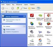
You can view the version of the SLIC table in the BIOS using a specialized utility RW - Read & Write Utility (current version 1.4.7), which can be downloaded from the website http://rweverything.phpnet.us. This utility is also called RW-Everything.
Having installed this utility, launch it and in the main program window on the toolbar, click on the button labeled ACPI. In the ACPI Table window that opens, click on the SLIC tab. Next, you need to look at the table in hexadecimal format and find in it a line starting with byte 53 20. If the next four bytes are 00 00 00 00, then the SLIC table version 2.0 is flashed in the BIOS, and if - 01 00 02 00, then the SLIC is flashed. version 2.1 table (fig. 3).

Rice. 3. Determining the version of the BIOS SLIC table
Of course, inserting the SLIC table into the BIOS is far from the only possible modding option. Another modding method is to unlock some of the BIOS functions. Indeed, motherboard manufacturers often deliberately block some BIOS functionality in order to simplify the BIOS setup procedure. They also disable those functions that are absent in a particular motherboard, but can be used in the following modifications.
Using specialized utilities, you can try to unlock all disabled features and options in the BIOS. In addition, you can change the logos (some motherboard manufacturers, for example, ASUS, even supply special utilities for changing the BIOS logo), as well as some names so that, for example, when loading, not the real name of the processor is displayed, but something like “AMD Core i9 -995 ".
There is another example of BIOS modding. Some craftsmen manage to unlock the ability to use the SLI mode for NVIDIA video cards through the BIOS on those motherboards where this mode is not provided. Actually, if a motherboard officially supports SLI mode, then its BIOS contains a corresponding key from NVIDIA. The idea of modding is to cut this key from the BIOS of the board on which SLI mode is officially supported, and insert it into the BIOS for the board on which SLI mode is not supported (that is, in the BIOS without an NVIDIA key). In particular, there are examples of how, due to such modding, the SLI mode was activated on motherboards based on the Intel P45 Express chipset.
However, let's move from theory to practice and discuss BIOS editing, in particular, AMI BIOS editing as the most common one.
Editing AMI BIOS
To edit the BIOS with the AMI kernel, you will need the AMIBCP utility, which, by the way, is released by the AMI company itself. This utility can be downloaded either separately or as part of the AMI BIOS ROM Utilities package. It should be noted that since, as we have repeatedly emphasized, manufacturers of motherboards and laptops make changes to the AMI BIOS for their products, there is no guarantee that the AMIBCP utility will recognize the BIOS. Alas, not every BIOS can be modified. As practice shows, BIOSes of ASUS and ECS boards can be edited without any problems, but AMIBCP is powerless with regard to boards from Gigabyte and MSI.
So let's get back to reviewing BIOS editing when possible. The AMIBCP utility (version 3.x) is launched from under the Windows operating system, but it should be noted that there are variants of the same utility for DOS.
After downloading the utilities, you need to open the BIOS file. In our example, we will consider editing the AMI BIOS for the ASUS P6X58D-E motherboard using the AMIBCP v.3.37 utility. We will edit the P6X58DE.ROM file.
So, in the main window of the program, load the BIOS file, which we will modify (Fig. 4).

Rice. 4. The main window of the AMIBCP v.3.37 utility
First of all, the Setup Configuration tab is interesting, in which, in fact, the BIOS settings are modified. The left window of this tab displays the main BIOS settings menu. If you uncheck a menu item, it will not appear in the BIOS menu. In the considered example (see Fig. 4), we unchecked the Ai Tweaker and Advanced items, thereby blocking all the options for overclocking the system. That is, the BIOS menu items, in which you can view information about the processor and memory, as well as change frequencies, supply voltage, etc., will simply be absent in the modified BIOS version.
The situation is similar when expanding the tree structure of each item in the BIOS setup menu: if you uncheck a sub-item, it will not be displayed in the BIOS menu. For example, if we do not want the Intel PPM Configuration item to be displayed in the Advanced settings menu, we just need to uncheck the corresponding item (Fig. 5).

In order to block any option in the BIOS setup menu, it is enough to set the value No. in the Show column for the corresponding item. Such locked elements will be (after saving the changes made) highlighted with a green stripe.
For example, if our system does not have additional fans in the case and we do not want their settings items to be displayed in the BIOS, then we enter the Power menu, then open the Hardware Monitor menu and for the Chassis Fan 1 Speed, Chassis Fan 2 Speed options, Set the Chassis Fan 3 Speed, Chassis Q-Fan Profile and Power Fan Speed to No in the Show column (Fig. 6).

Rice. 6. Blocking the BIOS from displaying various setup menu options
It should be noted that BIOS P6X58DE.ROM for ASUS P6X58D-E does not allow any improvements using the AMIBCP v.3.37 utility. All options are unlocked in it, so the maximum that can be done is to block what is not needed (although it is not clear why this should be done).
You can also try to change some of the labels, but keep in mind that the labels will not be displayed in Russian. For example, if we want the ComputerPress P6X58D-E BIOS Edition line to be displayed instead of the ASUS P6X58D-E ACPI BIOS Revision 0106 line at boot, then it is enough to find the ASUS P6X58D-E ACPI BIOS Revision 0106 line on the BIOS Strings tab and change it to the specified ...
It remains for us to consider one more type of BIOS modding - changing the background image (logo) of the BIOS. At the same time, ASUS even equips its motherboards with a special utility that allows you to implement this feature. Of course, this utility is the easiest to use for ASUS motherboards. However, for AMI BIOS, you can also use the OEM LOGO utility from AMI itself (Fig. 7).

Rice. 7. Changing the BIOS logo using the OEM LOGO utility
The interface of this utility is very simple and requires no comments. It is enough to load the BIOS and specify the path to the file with the new logo. The only limitation is that the picture must be of a certain resolution and format.
Actually, the original method, equipment and microcodes can be found (directly the AMI instruction), and in most cases the use of this method does not pose any problems and has no pitfalls, but in my practice I regularly encountered the following problem:
Those. there was a banal lack of free space inside the image. When you modify the BIOS for yourself for a specific processor, you can ignore this, because You can always load just one microcode specifically for your processor, or delete some old microcode to free up space, but when you modify it with a stream, you need to look for another compromise solution.
As a compromise, I chose the following solution - we take the latest microcode versions for all processors of the CORE generation in all constructs (Celeron E, Pentium E, Core 2 Duo, Core 2 Quad, Xeon * 3xxx / * 5xxx) and replace them with everything that came before ... The set of microcodes turned out to be the following:
The volume of this set is only 76 kilobytes. This file was obtained by combining these files:
cpu00010676_plat00000001_ver0000060f_date20100929.bin
cpu00010676_plat00000004_ver0000060f_date20100929.bin
cpu00010676_plat00000010_ver0000060f_date20100929.bin
cpu00010676_plat00000040_ver0000060f_date20100929.bin
cpu00010677_plat00000010_ver0000070a_date20100929.bin
cpu0001067a_plat00000011_ver00000a0b_date20100928.bin
cpu0001067a_plat00000044_ver00000a0b_date20100928.bin
cpu000006f2_plat00000001_ver0000005d_date20101002.bin
cpu000006f6_plat00000001_ver000000d0_date20100930.bin
cpu000006f6_plat00000004_ver000000d2_date20101001.bin
cpu000006f7_plat00000010_ver0000006a_date20101002.bin
cpu000006f7_plat00000040_ver0000006b_date20101002.bin
cpu000006fb_plat00000001_ver000000ba_date20101003.bin
cpu000006fb_plat00000004_ver000000bc_date20101003.bin
cpu000006fb_plat00000010_ver000000ba_date20101003.bin
cpu000006fb_plat00000040_ver000000bc_date20101003.bin
cpu000006fd_plat00000001_ver000000a4_date20101002.bin
The modification procedure itself has also changed slightly and has become, if not simpler, then faster:
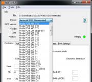
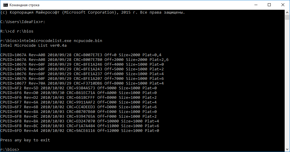
Step 1- open the BIOS image in the MMTool program: 

Step 2- to check, go to the last tab (CPU PATCH) and see the number of microcodes. Here, for example, there are 31 of them: 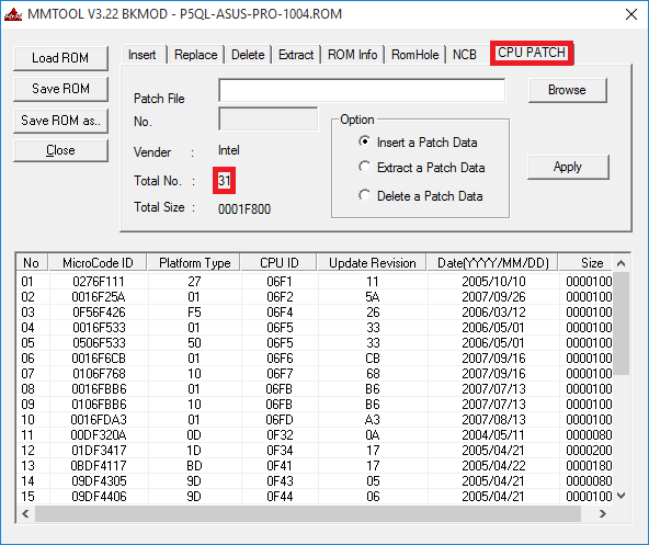
Step 3- go to the Replace tab and look for the item "P6 Micro Code" on it: 
Step 4- by selecting the "P6 Micro Code" item, press the Ikschtsyu button, select the ncpucode.bin file described above and replace it with the Replace button: 


Step 5- to check, go to the last tab (CPU PATCH) and look at the number of microcodes. After the replacement of microcodes, there are 17 left, the latest version: 
There is no fundamental difference with the modification order described on delidded.com. In most cases, the output is of course not the same, but the processor receives the required microcode. Of the subjective positive aspects, I would like to draw your attention only to the fact that the microcodes are guaranteed to be updated for all current processors, be they "civil" or "server" ones, and there is practically no risk of receiving a message about a lack of space. Although, in my practice, even for such a set of microcodes, there was not enough space a couple of times, it was with the BIOS for the ECS P4M900T-M and ECS P4M900T-M2 boards, which are generally compatible with the Xeon E5450.
By tradition, I publish a link to the archive with tools - (zip, 234KB). The archive contains the executable file MMTOL.exe(version 3.22 BKMOD), microcode file for all 45 / 65nm core / xeon processors ncpucode.bin, as well as two files 45nm.bin and 65nm.bin with microcodes only on 45nm processors and only on 65nm. The use of these files can be useful in cases where it is necessary to free up additional space in the BIOS, for example, for new firmware of some controller, network, disk, etc.
! NB: Neither ncpucode.bin file nor 45nm.bin / 65nm.bin files support Pentium 4, Celeron (without letter indices), Pentium D, Celeron D and Xeon W processors (Xeon 5080 for example). These are NetBrust generation processors.